You know what’s been missing from my life?

Yup.  Microcontrollers.

I got this idea several months back to create a few two-in-one effects pedals.  I had an EA Tremolo board and a one-knob reverb ready to go, and I thought they might pair nicely.  While I was doing the layout for the 1590BB enclosure I thought it would be cool if the pedal ran in two modes: Separate Mode, where each switch activated it’s own affect; and Together Mode, where the right switch activated both effects simultaneously.  I spent days thinking about this and mocking up switch diagrams, but all to no avail.  It was too complicated for me to figure out — at least with some room left in the enclosure for the actual effects boards.  For a while I had a brilliant plan to use optoisolators, and while they do simplify things, the switching was still a catastrophe.  That’s when I broke down and started thinking about microcontrollers.

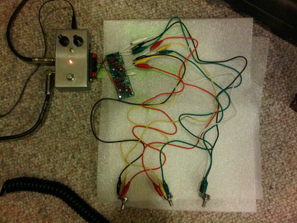
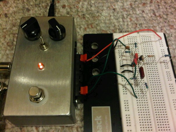
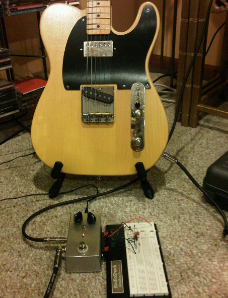
Two weeks later, I have an Arduino Uno and a working prototype on breadboard.

arduino-dual-switch

Arduino Dual-Effect Superswitch

With the added flexibility of the microcontroller, I’ve added a third mode: XOR Mode.  Very exciting!  More details to come….

Three-Mode Dual-Effect Superswitch Prototype_bb

I stumbled across the schematic for Dead Easy Dirt the other day and (a.) it looked like something fun and easy to breadboard, and (b.) it got me thinking about diode clipping.  I cranked out and tested the original schematic last night — basically just an op-amp set for maximum gain straight into symmetrical diode clipping.  It was god-awful, but pretty much what I expected.  The more I monkeyed around with it, the more I caught myself wondering if this was related to the old ProCo RAT circuit.  Sure enough, it’s almost exactly the heart of a RAT using a different op-amp and minus any tone shaping or buffers.*  Cool.

I played around with several diode variations, but ripping them out of and stuffing them back into the breadboard was getting tiresome.  The solution: Simon and I ran to Radio Shack after our coffee date this morning and picked up an eight-position dipswitch.  I spent about a half hour this afternoon reworking the board with the switches, and now I’ve got 16 varieties of diode clipping goodness on tap.

Switch Positions:

  1. 1N4001, anode to ground (because I have a million 1N4001’s lying around)
  2. Red LED, anode to ground (lights up more the harder you drive it — fun!)
  3. Nothing (for single-sided assymetrical clipping, kinda redundant)
  4. 1N914, anode to ground (the original RAT diode)
  5. 1N4001, cathode to ground
  6. Red LED, cathode to ground
  7. Two 1N914’s in series, cathode to ground (for double-sided assymetrical clipping)
  8. 1N914, cathode to ground

Select one switch from switches 1-4 and another from 5-8 and you’re in trashy distortion heaven!

—–

* Also seen in the MXR Distortion+, and I’m sure several other distortion pedals.  So-called overdrive pedals frequently use diode clipping, too, but tend to put it in a less intrusive portion of the signal-shaping circuit.

Inspired by the Beavis Board and other similar designs, I finally got around to building my own effects circuit test box.

+9VDC in from an adapter goes to a MadBean Road Rage board, which uses a TC1044 and a voltage regulator to provide 9V, 12V, ~18V and -9V — the leftmost knob is a rotary switch. Power then goes to a voltage sag knob before it heads to the outside world.

I used a four-output speaker connection panel from Radio Shack for my connections to the external circuit. From top to bottom it goes: power, ground, circuit input, circuit output. The 1PDT switch is there to select whether circuit output or test probe output goes to the out-to-amplifier jack, but I haven’t wired in the test probe yet.

To test the test box, I connected an old BYOC Confidence Booster board I had lying around. Worked like a charm.

Here I am testing Channel 1 of my MadBean Aristocrat board. Sounds great configured for overdrive with a B250K Gain pot. I’ll try the B100K later today.

It’s great to “rock it before you box it”. Not only do you make sure the circuit is functional before you spend a lot of time cramming the board into the enclosure and wiring up the jacks and the switches, but you can make subtle tweaks much more easily, too.

Of course if you really wanna tweak an effects circuit before you even heat up your soldering iron, you can breadboard it first. A friend of mine has expressed interest in the Echoplex preamp booster, so I put this together last night. (Notice that I have the voltage selector knob on the left in 18V position.)

It’s essentially the schematic for the MadBean FatPants board, but I replaced all the potentiometers with median-value resistors.

The problem with working on these guitar projects at night is that, unless you live by yourself in an underground bunker, you can never properly test them at serious volume when you’re finished. I could tell there was a boost, but I couldn’t tell how much it was fattening up the sound or if I even liked it.

Sounded great this morning when I finally had a chance to crank up the amp! I’ll grab some pots and alligator clip leads and head over to my friend’s place later this week to see if he likes it.