- Published:July 23rd, 2011
- Comments:No Comments
- Category:Projects
I stumbled across the schematic for Dead Easy Dirt the other day and (a.) it looked like something fun and easy to breadboard, and (b.) it got me thinking about diode clipping. I cranked out and tested the original schematic last night — basically just an op-amp set for maximum gain straight into symmetrical diode clipping. It was god-awful, but pretty much what I expected. The more I monkeyed around with it, the more I caught myself wondering if this was related to the old ProCo RAT circuit. Sure enough, it’s almost exactly the heart of a RAT using a different op-amp and minus any tone shaping or buffers.* Cool.
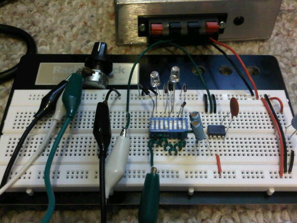
I played around with several diode variations, but ripping them out of and stuffing them back into the breadboard was getting tiresome. The solution: Simon and I ran to Radio Shack after our coffee date this morning and picked up an eight-position dipswitch. I spent about a half hour this afternoon reworking the board with the switches, and now I’ve got 16 varieties of diode clipping goodness on tap.
Switch Positions:
- 1N4001, anode to ground (because I have a million 1N4001’s lying around)
- Red LED, anode to ground (lights up more the harder you drive it — fun!)
- Nothing (for single-sided assymetrical clipping, kinda redundant)
- 1N914, anode to ground (the original RAT diode)
- 1N4001, cathode to ground
- Red LED, cathode to ground
- Two 1N914’s in series, cathode to ground (for double-sided assymetrical clipping)
- 1N914, cathode to ground
Select one switch from switches 1-4 and another from 5-8 and you’re in trashy distortion heaven!
—–
* Also seen in the MXR Distortion+, and I’m sure several other distortion pedals. So-called overdrive pedals frequently use diode clipping, too, but tend to put it in a less intrusive portion of the signal-shaping circuit.


No Comments
No comments yet.